
What makes residential HVAC plans code-compliant?
A code-compliant HVAC plan set connects the home’s calculated loads to the selected equipment and the duct system, then documents the assumptions clearly enough for the local reviewer and installer to follow.
Direct answer: For many residential projects, the core design path is a Manual J load calculation, followed by Manual S equipment selection, with Manual D duct design when duct sizing and distribution documentation are required. The exact submittal still depends on the code edition and the local authority having jurisdiction.
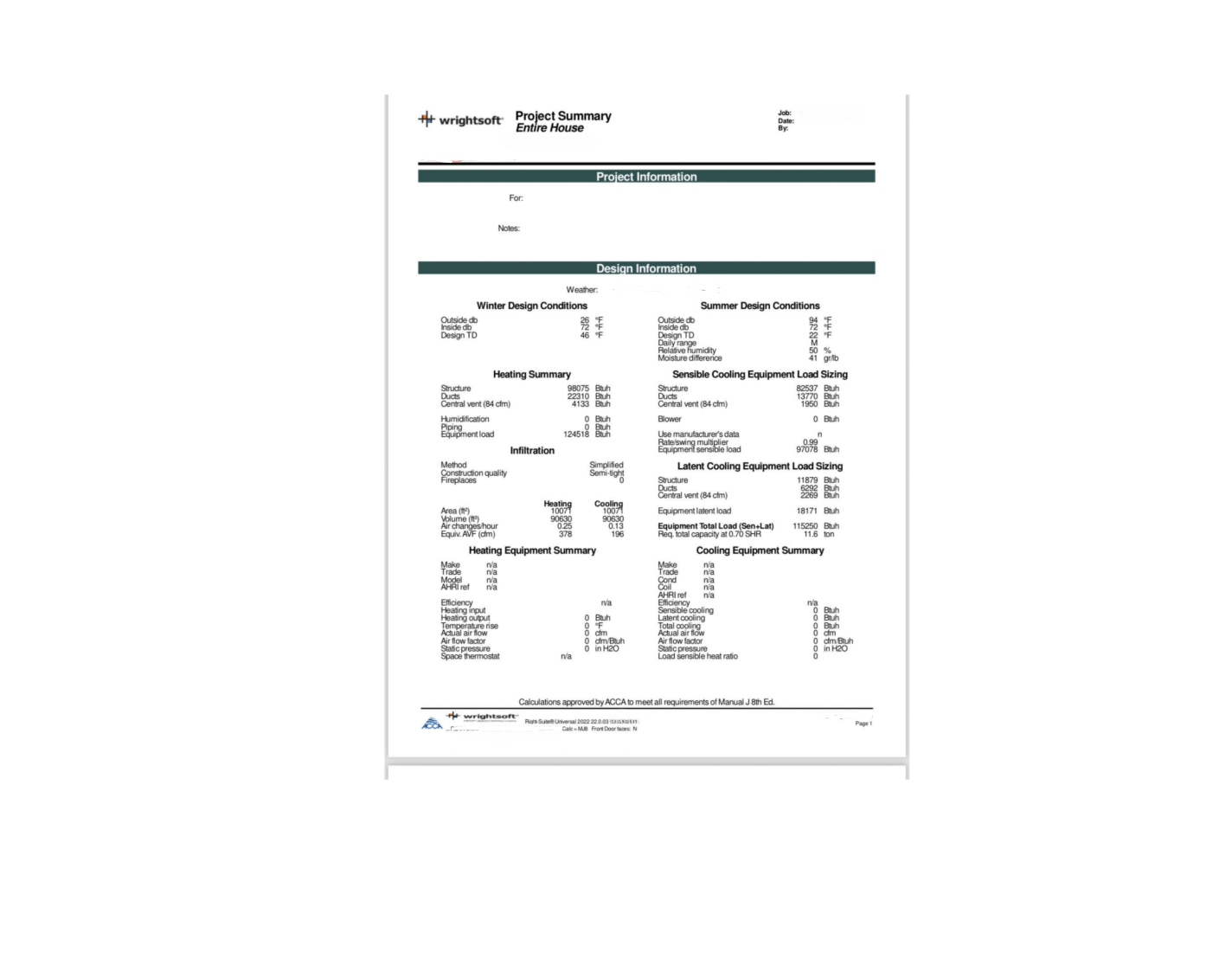
Code compliance is a chain, not a single report.
A load calculation can be accurate and still leave the project incomplete if the equipment was never checked against manufacturer data or the duct system cannot deliver the required airflow.
Manual J: determine the building loads
The home is modeled using location, orientation, construction assemblies, insulation, glazing, infiltration, ventilation, ducts, and internal gains. The result should include both whole-house and room-by-room loads when room airflow is part of the design.
How Manual J works →Manual S: select actual equipment
Nominal tonnage is not enough. Manual S uses manufacturer performance data to verify heating capacity, total cooling capacity, sensible cooling capacity, latent performance, and airflow at the project’s design conditions.
How Manual S works →Manual D: design the ducts
Manual D uses room airflow requirements, blower data, available static pressure, fitting losses, duct lengths, and the selected equipment airflow to size the supply and return system.
How Manual D works →Why this order matters: Manual S cannot repair an inaccurate Manual J, and Manual D cannot deliver room-by-room comfort if the equipment airflow and room loads were never established.
How a residential HVAC plan set comes together.
Review the plans
Floor plans, elevations, sections, schedules, location, orientation, and construction details are checked for conflicts or missing information.
Model the home
Rooms, walls, windows, ceilings, floors, exposure, infiltration, ventilation, and duct conditions are entered into the calculation software.
Calculate loads
Heating, sensible cooling, latent cooling, and room-by-room airflow requirements are documented through Manual J.
Select equipment
Manufacturer data is compared with the loads using Manual S rather than choosing equipment by nominal size alone.
Design and document
Duct sizes, airflow, equipment schedules, notes, and reports are assembled according to the project scope and reviewer requirements.
What should be included in residential HVAC plans?
The answer depends on the jurisdiction, project type, and adopted code. A useful residential HVAC package commonly includes enough information to verify that the building load, equipment, and distribution system agree with one another.
- Project address and climate/design location
- Indoor and outdoor design conditions
- Building orientation and room geometry
- Wall, roof, ceiling, floor, window, and door assumptions
- Infiltration and ventilation inputs
- Whole-house heating and cooling loads
- Room-by-room loads and airflow where required
- Manual S equipment selection information
- Manufacturer model numbers and performance data
- Duct sizes, airflow, and design criteria when included
- Supply and return locations or schedules when required
- Notes identifying assumptions and project limitations
Do not assume every permit office wants the same package. One jurisdiction may accept Manual J and Manual S reports, while another may also require duct plans, ventilation documentation, equipment schedules, energy forms, or locally formatted worksheets. Confirm the local checklist before treating any national template as complete.
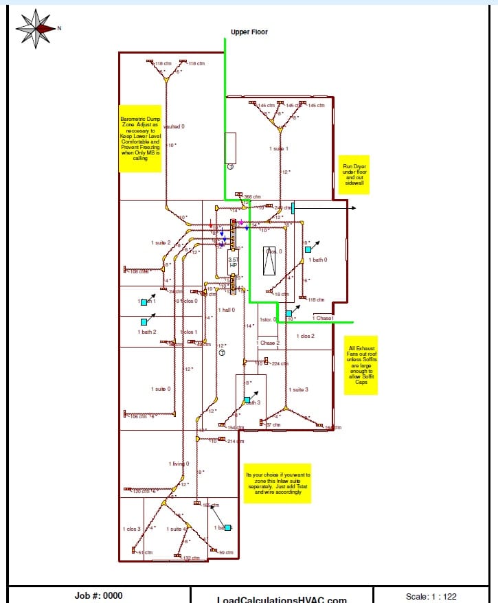
What each document proves—and what it does not.
| Document | Primary question | What it should show | What it does not replace |
|---|---|---|---|
| Manual J | What are the heating and cooling loads? | Building inputs, design conditions, whole-house and room loads, sensible and latent cooling | Equipment performance verification |
| Manual S | Does the proposed equipment match the loads? | Manufacturer performance at design conditions, heating capacity, sensible and total cooling capacity | Duct sizing and room airflow delivery |
| Manual D | Can the system deliver the required airflow? | Airflow assignments, available pressure, effective length, duct sizes, fittings, supply and return design | The load calculation or equipment selection |
| Mechanical plan | How is the selected system represented on the project documents? | Equipment, ducts, grilles, notes, schedules, ventilation, and project-specific details | The supporting calculations behind the plan |
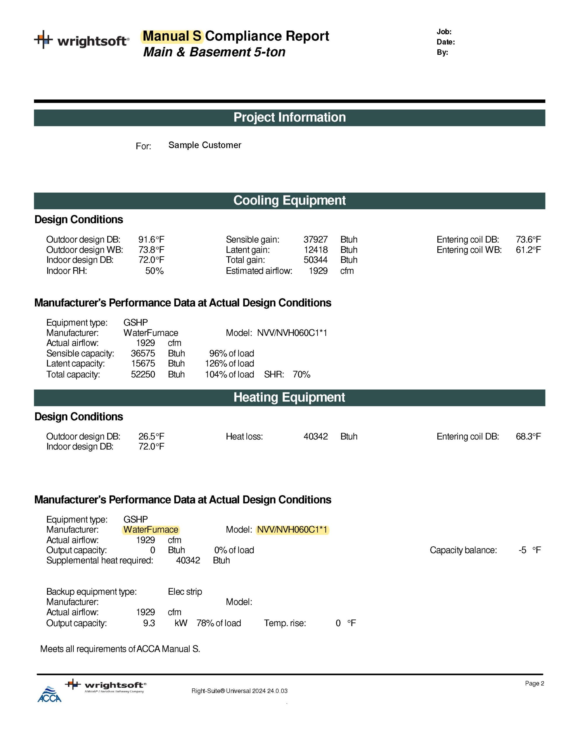
Why HVAC plans get questioned.
The equipment does not match the calculation.
The plan lists equipment, but there is no Manual S documentation—or the selected capacity does not align with the heating, sensible, and latent loads.
The report cannot be traced to the plans.
Orientation, glazing, assemblies, ventilation, duct location, or design conditions are missing, contradictory, or clearly inconsistent with the construction documents.
The ducts are shown without design support.
Room airflow, available static pressure, fitting losses, return-air strategy, or duct sizes are not connected to a documented Manual D process.
A clean drawing is not automatically a compliant design. The drawings and reports must agree. If the load calculation, equipment schedule, and duct plan point to different systems or airflow values, formatting will not solve the underlying conflict.
Approved software is necessary. Good inputs are still the deciding factor.
Professional load-calculation software applies the formulas, tables, weather data, and procedures required by the selected method. It can organize room loads, equipment data, and duct calculations far more efficiently than a manual worksheet.
It still cannot decide whether a plan note overrides a schedule, whether the north arrow is wrong, whether an attic is truly inside the conditioned envelope, or whether the ventilation assumptions match the mechanical scope. Those are review decisions.
That is why the quality of a code submittal depends on both the software and the human interpretation of the project information.
Our workflow: We use Wrightsoft for residential load calculations, equipment selection, and duct-design work. The reports are built from the project plans and known construction information, with assumptions identified when the plans do not answer a required question.
Code-compliant HVAC plans FAQ
What are code-compliant HVAC plans?
Code-compliant HVAC plans are project documents and supporting calculations prepared to meet the adopted residential code and the local review requirements. They commonly connect Manual J loads, Manual S equipment selection, and Manual D duct design, but the exact submittal varies by jurisdiction.
Are Manual J, Manual S, and Manual D always required?
They are widely referenced in residential codes and permit processes, but the exact documentation required for a specific project depends on the adopted code, project type, and local authority having jurisdiction. Confirm the local checklist before submitting.
Can a Manual J report be used without Manual S?
A Manual J report establishes the loads, but it does not by itself prove that a proposed equipment model matches those loads. Manual S is the equipment-selection step that compares manufacturer performance data with the calculated requirements.
Does a duct drawing automatically satisfy Manual D?
No. A drawing can show duct routes without documenting room airflow, available static pressure, total effective length, fitting losses, duct sizes, or the calculation process used to reach those sizes. Manual D is the design method behind the drawing.
What information is needed to prepare residential HVAC plans?
Typical inputs include floor plans, elevations, sections, window and door schedules, insulation and assembly details, project location, orientation, ventilation information, equipment preferences, and any permit checklist supplied by the local jurisdiction.
Can one plan set work for every jurisdiction?
No universal plan set is guaranteed to satisfy every reviewer. National methods provide the design foundation, but local jurisdictions can require specific forms, notes, equipment schedules, energy documents, ventilation information, or drawing conventions.
How do I start a permit-plan project?
Use the pricing and project-start page to choose the needed Manual J, Manual S, or Manual D service and submit the available plans. Include the local permit checklist when one is available.
Continue through the residential design process.
The full pillar guide connecting building loads, equipment, climate, and airflow.
Open the complete guide →Room-by-room and whole-house heating and cooling load calculations.
Explore Manual J →Residential equipment selection using manufacturer performance data.
Explore Manual S →Duct sizing, airflow distribution, static pressure, and effective length.
Explore Manual D →Understand where the calculated loads come from in a residential building.
Understand the loads →How controlled ventilation interacts with infiltration and HVAC loads.
Read the ventilation guide →Why large exhaust systems require pressure and makeup-air planning.
Read about makeup air →Latent load, ventilation air, moisture removal, and humid-climate sizing.
Explore hot-humid design →Climate-specific residential load-calculation resources across the United States.
Browse areas served →Build the permit package from the building outward.
Send the plans, construction details, equipment information, and any local permit checklist. We will review the scope and prepare the selected residential Manual J, Manual S, and Manual D documents.