
HVAC Load Calculations, Done the Right Way
Room-by-room heating and cooling loads, equipment matched to real performance, and duct design that actually delivers comfort — built around ACCA Manual J, Manual S, and Manual D for homes, not commercial buildings.
When we say HVAC load calculations, we mean the full residential design chain: Manual J to calculate the load, Manual S to choose equipment that matches the load at real design conditions, and Manual D to design ductwork that delivers the required airflow.
We use Wrightsoft Right-Suite for residential Manual J, Manual S, and Manual D work, and this page stays strictly residential — no Manual N, no Manual T, and no commercial load calculation language.
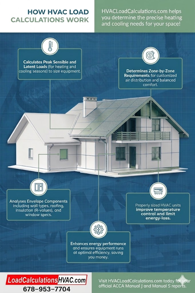
The three parts of proper HVAC load calculations
This page works as the parent hub above the individual service pages, so it shows how Manual J, Manual S, and Manual D connect instead of treating them like separate disconnected tasks.
Room-by-room heating and cooling loads
Manual J HVAC load calculations determine how much heating and cooling each room in the house actually needs based on construction details, windows, orientation, infiltration, duct losses, and internal gains.
This is the foundation for proper HVAC design, and it replaces square-foot rules of thumb with a documented residential method.
Go to Manual J →Equipment matched to the calculated loads
Manual S equipment selection uses the Manual J results and matches them to manufacturer performance data so the selected equipment fits the real heating, sensible cooling, and latent cooling requirements.
That matters because nominal tonnage alone does not tell you how a system performs at your design conditions.
Go to Manual S →Duct design that delivers the airflow
Manual D duct design takes the selected system and the room-by-room loads and turns them into actual trunk sizes, branch sizes, and airflow targets for the house.
The point is simple: the comfort calculated on paper should show up in the real rooms after installation.
Go to Manual D →How we model the house
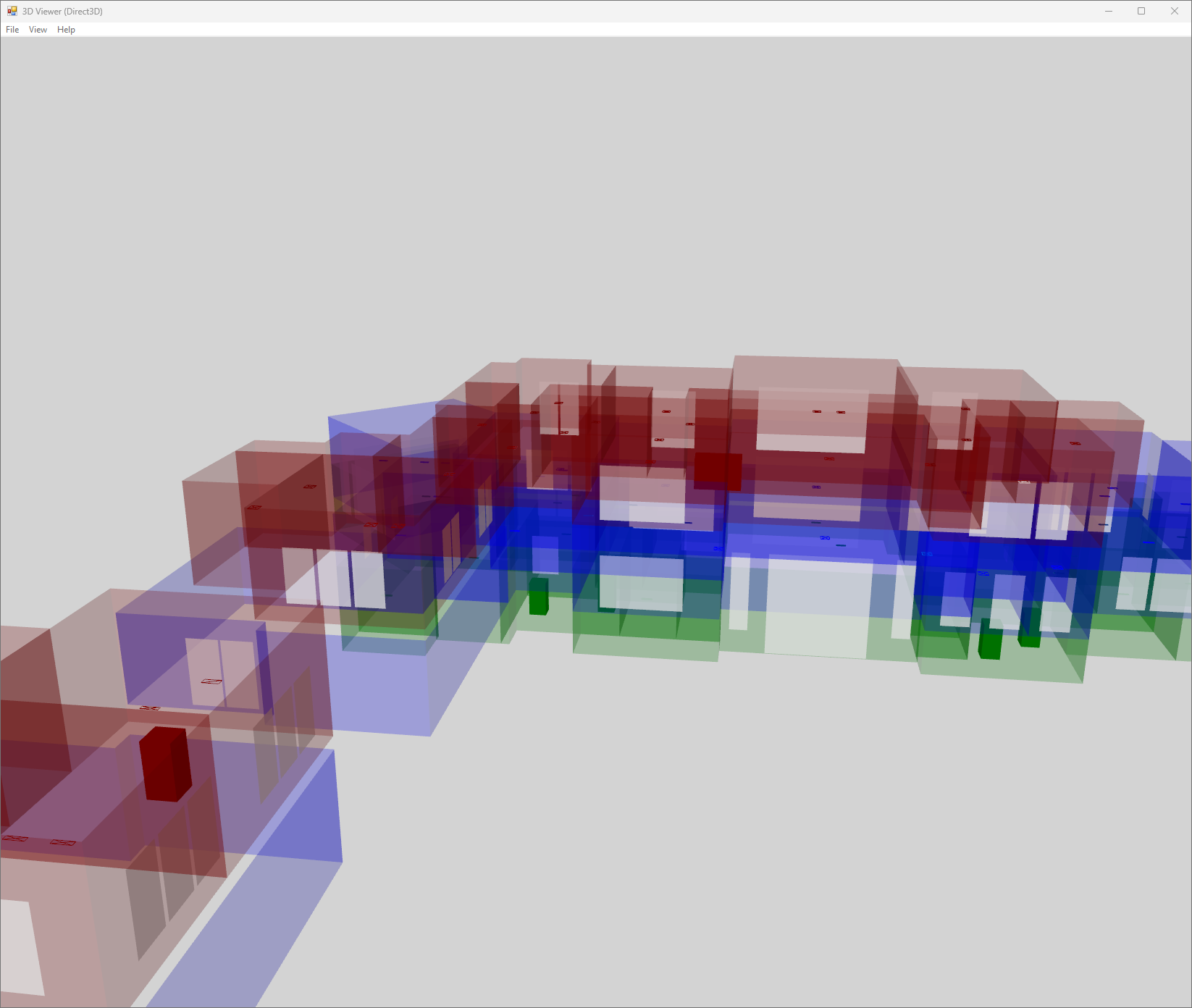
We begin by rebuilding the home in residential HVAC software using the plans and construction details: room geometry, exterior surfaces, windows and doors, roof and ceiling assemblies, floors, and the distinction between conditioned and unconditioned spaces.
This 3D room-by-room model is what allows us to calculate heat gain, heat loss, airflow needs, and equipment sizing with much more precision than a rough area-based shortcut.
That same model supports related topics across the site, including heat gain and heat loss, airtight homes and ventilation, and hot-humid climate load calculations.
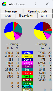
Where the loads actually come from
Manual J does more than produce a total number. It shows how the load is distributed across walls, windows, doors, ceilings, floors, air infiltration, ducts, ventilation air, and internal gains so you can see what is driving the system size.
- Solar gain through glazing can dominate cooling loads in many homes.
- Air leakage and ventilation air add both sensible and latent cooling burden.
- Duct losses matter, especially when ducts run through harsh attic or crawlspace conditions.
- Internal loads from people, lighting, and appliances still contribute and must be counted.
This is why proper HVAC load calculations connect directly to envelope strategy, ventilation planning, and humidity control — not just equipment tonnage.
Wrightsoft reports and documentation
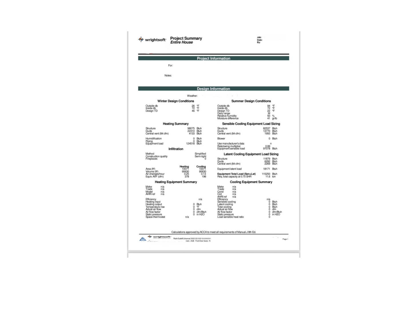
We use Wrightsoft Right-Suite to generate the residential reports that support the design process, including Manual J summaries, equipment selection documentation, and the information that flows into duct design.
That creates a clear paper trail from the model, to the load, to the selected equipment, to the duct layout.
It also makes it easier to support permit review, builder coordination, and installation clarity on residential projects.
From load calculations to duct design
After the loads are calculated and the equipment is selected, the work still is not finished. The duct system has to be designed so each room receives the airflow it was assigned in the room-by-room load model.
That is why this hub connects directly to Manual D duct design, load calculation software, and range hood makeup air topics that affect pressure balance, ventilation, and system behavior in real homes.
When the airflow side is ignored, even a correctly selected unit can still leave some rooms uncomfortable.

Related residential HVAC pages
This page supports the rest of your content cluster, so these internal links stay close to the actual residential design process.
Frequently asked questions
What is an HVAC load calculation?
An HVAC load calculation is the residential process used to determine how much heating and cooling a home needs, room by room, using Manual J rather than a square-foot rule of thumb.
What is the difference between Manual J, Manual S, and Manual D?
Manual J calculates the room-by-room heating and cooling loads, Manual S selects equipment that matches those loads using manufacturer data, and Manual D designs the duct system to deliver the required airflow to each room.
Do you handle Manual N or Manual T projects?
No. This page and service stack are residential only and focus on Manual J, Manual S, and Manual D.
What do you need to complete residential HVAC load calculations?
Typical inputs include floor plans, window and door details, insulation and assembly information, project location, orientation, and any special conditions that change the loads from room to room.
Can you help with hot-humid climates?
Yes. Residential HVAC load calculations for hot-humid climates pay close attention to latent load, ventilation air, and humidity control.
Start your residential HVAC load calculations
If you need permit-ready Manual J, Manual S, and Manual D work for a new home, renovation, or replacement project, this page is designed to lead visitors into the right next step while keeping the same font and color system across your site.
See pricing and start your project →