
Manual D Duct Design Done Right: What the Numbers Actually Mean
Most comfort complaints that survive equipment replacement are duct problems. The system is right. The pipes aren’t. Here’s what Manual D actually calculates and where duct design most often fails.
A Manual J load calculation tells you the heating and cooling demand per room. Manual S tells you which equipment meets that demand. Manual D answers the third question: can the duct system actually deliver what the equipment produces to every room that needs it? The answer is often no — not because the equipment is wrong, but because the ducts were sized by habit, not by the numbers.
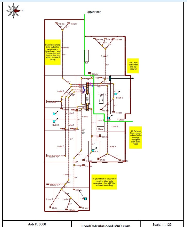
The available static pressure problem
Every duct system starts with a pressure budget. The blower produces total external static pressure — that’s the budget. Before a single foot of duct is sized, that budget is already being spent:
| Component | Typical pressure drop |
|---|---|
| Evaporator coil | 0.15–0.25 IWC |
| Filter (clean, MERV 8) | 0.05–0.10 IWC |
| Filter (loaded or MERV 13) | 0.15–0.30 IWC |
| Supply grilles and registers | 0.03–0.05 IWC |
| Return grilles | 0.03–0.05 IWC |
If the blower is rated at 0.50 IWC and the coil, filter, and grilles consume 0.40 IWC, only 0.10 IWC remains for the entire duct system. A Manual D calculation works within that remaining pressure budget. This is also why high-MERV filters create comfort problems in systems never designed for them — a MERV 13 filter loaded with a month of dust can consume twice what a clean MERV 8 does. That resistance comes directly out of the airflow delivered to every room.
Total effective length: why straight duct isn’t what you’re sizing
Manual D uses total effective length (TEL) — physical run plus the equivalent length fittings add. Every fitting adds resistance that behaves exactly like additional straight duct:
| Fitting type | Equivalent length added | Why it matters |
|---|---|---|
| 90° radius elbow, 8-inch round | ~15 feet | Every bend is another 15 feet of friction |
| 90° square-throat elbow | ~50–60 feet | Four times worse than radius — never use them |
| Plenum takeoff, sharp | ~30–50 feet | Highest-resistance fitting in most systems |
| Swept takeoff, conical entry | ~5–10 feet | The right way to tap a trunk |
| Register boot, floor 90° | ~25–50 feet | Often the largest resistance item in a branch |
| Flex duct vs. sheet metal | +25–30% friction | Even when installed perfectly |
A branch run that’s 20 physical feet long with three radius elbows and a register boot might have a TEL of 90–100 feet. A run sized for 20 feet of straight duct will be badly undersized for 100 feet of effective length. That’s where rooms end up cold in January and hot in July despite a correctly sized system.

The flex duct reality
Flex duct is not wrong. It’s installed wrong constantly. When pulled tight, properly supported, with smooth bends, flex performs close to its design friction rate. When compressed, sagging, or bent sharply, its resistance can double or triple.
Return air: the side everyone ignores
Supply duct gets designed. Return duct gets guessed. That pattern causes more comfort problems than almost anything else. In a typical house with one central return, every closed interior door creates a room with supply air coming in and no path for that air to leave. The room pressurizes. The adjacent hall depressurizes. Static pressure rises, total airflow drops, and the rooms with closed doors — typically bedrooms — are the ones that complain most about temperature.
The fixes are well established: dedicated returns in each closable room, transfer grilles, jump ducts, or undercut doors large enough to pass the required CFM. Manual D establishes the minimum return area needed. Most installers guess it.
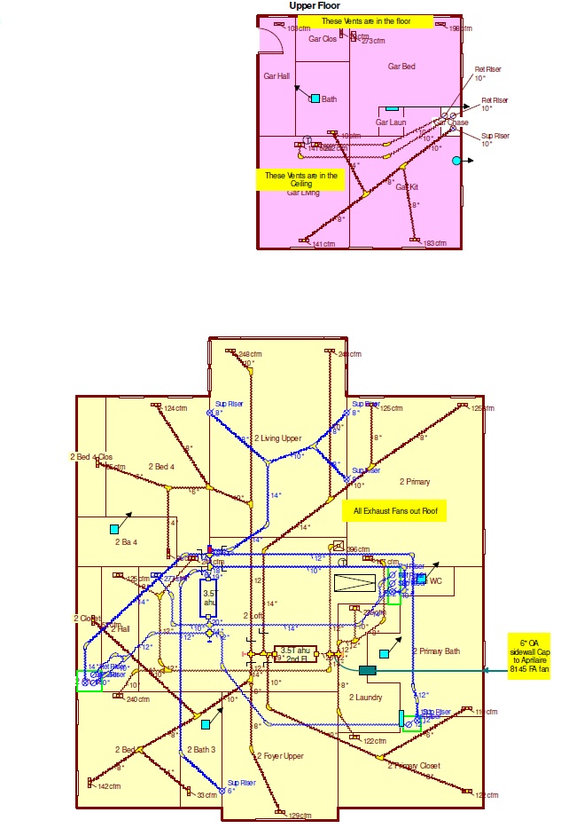
What a complete Manual D delivers
A properly done Manual D is not a sketch with duct sizes penciled in. It connects the load calculation to the equipment airflow to a specific, installable layout. It shows: room-by-room airflow from Manual J; equipment total airflow from Manual S; available static pressure including all accessories; friction rate; supply trunk sizing with taper where appropriate; individual branch run sizes with TEL calculations; return path sizing and locations; and register selection criteria. We produce this for residential and light commercial projects nationwide, in WrightSoft Right-D to current ACCA Manual D methodology.
Frequently asked questions
What is Manual D duct design?
Manual D is the ACCA method for sizing residential and light commercial duct systems. It starts with room-by-room airflow requirements from Manual J, equipment operating airflow from Manual S, and available static pressure from the blower, then calculates duct sizes that deliver the designed airflow to each room accounting for friction, fittings, and duct material.
What is available static pressure and why does it matter?
Available static pressure (ASP) is what remains from the blower’s total pressure after the coil, filter, grilles, and accessories take their share. It’s the pressure budget for the duct system. If the ASP is 0.10 IWC and you size ducts assuming 0.20 IWC, the system will never deliver the designed airflow.
What is total effective length?
Total effective length (TEL) is the physical duct run plus the equivalent length fittings add. A 90-degree radius elbow in 8-inch duct adds roughly 15 feet of equivalent resistance. A square-throat elbow adds 50 feet or more. TEL is what you size against — not the straight-line distance from the air handler to the register.
Is flex duct acceptable in a Manual D design?
Yes, when properly installed. Flex has higher friction rate than sheet metal and must be pulled tight and free of compression. Manual D accounts for this in the calculation. Problems arise when flex is compressed at fittings or allowed to sag, which can double or triple actual resistance.
Do you provide Manual D for light commercial?
Yes — residential primarily, with select light commercial including small offices, recreation centers, and similar occupancies. Same ACCA Manual D methodology, same permit-ready output.
A duct design that connects the load to the equipment to an installable layout — sized from actual room loads and real available static pressure, not from habit.
See pricing & get started →